 omldeen
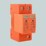
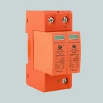
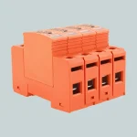
Product Description

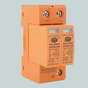
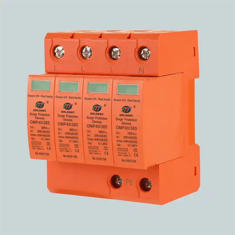
OMP series DIN-rail surge protection device (SPD) is Class II / Type 2 (IEC 61643-11) pluggable surge protector, designed for low-voltage power supply system protection against the damage from surges and spikes caused by lightning and other electrical sources.features fail-safe and self-protected technology, offering quick thermal response and perfect cut-off function and providing fast and reliable protection for various power supply systems.
Functional Features
- Surge current of 40KA.
- Fast reaction speed, response time is less than 25ns.
- Flame retardant shell design, can be easily installed in 35mm electric rail.
- Waterproof IP20 rated.
- Visual alarm window color protection work state, green (normal), red (fault).
- CE & RoHS compliant.
- Accept OEM/ODM.
- Appearance/color can be changed according to customer needs.
Product application and installation location
This series of surge protective devices are suitable for class II lightning protection and over-voltage protection. They are used at the junction of lpz1 and lpz2 in lightning strike areas. They are usually installed in floor distribution box, computer center, telecommunication room, elevator control room, frequency conversion equipment control room, hospital operating room, monitoring room and distribution box in places with electronic medical equipment.
Electrical Specifications
| Model | OMP-APM40/385 |
| Rated working voltage(Un) L-N 50Hz/60Hz | 220VAC |
| maximum continuous operating voltage(Uc) | 385VAC |
| Nominal Surge current (In) | 20 KA(8/20μs) |
| Maximum Surge current (Imax) | 40 KA(8/20μs) |
| Response time (Ta) | ≤25 ns |
| Modes of protection | L-PE,N-PE;L-N,N-PE |
| Voltage protection level(Up) | ≤1.8KV |
| Leakage Current(LC) | ≤10μA |
| Follow current | MOV model: Nil; GDT model: 100A self cutoff |
| Operating status/fault indication | Internal: green – normal;red – failure |
| Test level(Category IEC/VDE/GB) | classII/C/T2 |
Mechanical Specifications
| Conductor cross section(L/N) | ≥6mm2 |
| Ground wire cross sectional | ≥10mm2 |
| Flammability | PBT @UL94 VO |
| Remote alarm contact (FM) | NO/NC/COM, Isolated Form C |
| Remote alarm contact capability Un/ln | AC: 250V/0.5A DC: 250V/0.1A; 75V/0.5A |
| Remote alarm contact connecting wire | Max. 1.5mm2 or #16AWG |
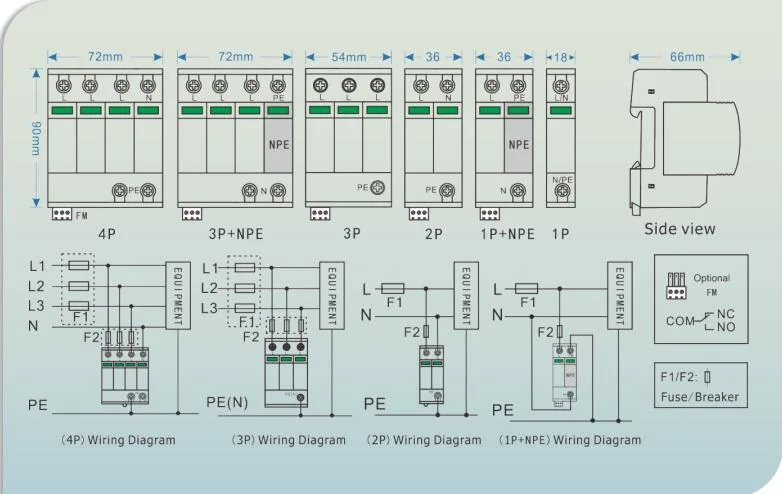
| Size | 1P:18*90*66mm 4P:72*90*66mm |
| Weight | 1P:115g ,4P:360g |
| Mounting | 35mm DIN-Rail |
Environmental Specifications
| Temperature Operating Range | -40 ~ +85ºC,Altitude≤4km |
| lngress Protection (IP) Rating | 30%~90% |
| waterproof rating | IP20 |
Other Information
| Compliance Certifications | CE, RoHs |
| Implementation of the standards | GB18802.11/lEC61643-11 |
| Order No. | 800156 |
Model list
| Type | Model | Power distribution system | Nominal Voltage | Maximum Continuous Operating Voltage Uc (Vac) | Voltage Protection Level Up (kV) | ||||
| Un@L-N(Vac) | L-N | L-G | N-G | L-N | L-G | N-G | |||
| OMP-APM40/150/2P | 2 | TN | 110/120 | – | 150 | 150 | – | 0.8 | 0.8 |
| OMP-APM40/150/1+N | 2 | TN/TT | 110/120 | 150 | – | 255 | 0.8 | – | 1.5 |
| OMP-APM40/275/2P | 2 | TN/TT | 220/230 | – | 275 | 275 | – | 1.2 | 1.2 |
| OMP-APM40/275/1+N | 2 | TN/TT | 220/230 | 275 | – | 255 | 1.2 | – | 1.5 |
| OMP-APM40/320/2P | 2 | TN/TT | 220-240 | – | 320 | 320 | – | 1.4 | 1.5 |
| OMP-APM40/320/1+N | 2 | TN/TT | 220-240 | 320 | – | 255 | 1.4 | – | 1.5 |
| OMP-APM60/340/2P | 2 | TN/TT | 220-240 | – | 340 | 340 | – | 1.5 | 1.5 |
| OMP-APM60/340/1+N | 2 | TN/TT | 220-240 | 340 | – | 255 | 1.5 | – | 1.5 |
| OMP-APM40/385/2P | 2 | TN | 220-240 | – | 385 | 385 | – | 1.8 | 1.8 |
| OMP-APM40/385/1+N | 2 | TN/TT | 220-240 | 385 | – | 255 | 1.8 | – | 1.5 |
| OMP-APM40/150/4P | 4 | TN | 110/120 | – | 150 | 150 | – | 0.8 | 0.8 |
| OMP-APM40/150/3+N | 4 | TN/TT | 110/120 | 150 | – | 255 | 0.8 | – | 1.5 |
| OMP-APM40/275/4P | 4 | TN/TT | 220/230 | – | 275 | 275 | – | 1.2 | 1.2 |
| OMP-APM40/275/3+N | 4 | TN/TT | 220/230 | 275 | – | 255 | 1.2 | – | 1.5 |
| OMP-APM40/320/4P | 4 | TN/TT | 220-240 | – | 320 | 320 | – | 1.4 | 1.5 |
| OMP-APM40/320/3+N | 4 | TN/TT | 220-240 | 320 | – | 255 | 1.4 | – | 1.5 |
| OMP-APM40/340/2P | 2 | TN/TT | 220-240 | – | 340 | 340 | – | 1.5 | 1.5 |
| OMP-APM40/340/1+N | 2 | TN/TT | 220-240 | 340 | – | 255 | 1.5 | – | 1.5 |
| OMP-APM40/385/4P | 4 | TN | 220-240 | – | 385 | 385 | – | 1.8 | 1.8 |
| OMP-APM40/385/3+N | 4 | TN/TT | 220-240 | 385 | – | 255 | 1.8 | – | 1.5 |
Product Size
Precautions for installation of surge protector
1. Surge protective devices are installed in parallel in the line.
2. Please do not connect the circuit in reverse or wrong way.
3. The closer the surge protector is installed at the front end of the protected equipment, the better the effect is.
4. The equipment needs regular inspection and must be replaced immediately after deterioration.
5. Remember not to work with live line.
6. The grounding must be good and the grounding resistance should not be greater than 4 Ω.
7. The front end of surge protector should be equipped with short circuit device to avoid fire caused by short circuit after deterioration of lightning protection device.